Rhode & Schwarz FK310H1 RemoteControl
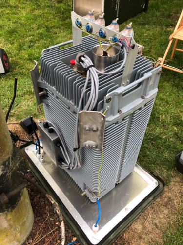
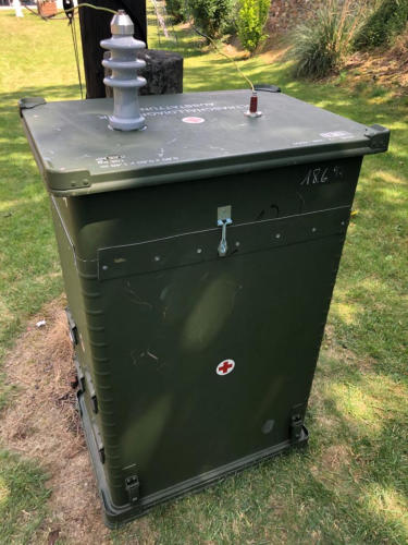
External / Out door view of Remote AntennaControl Unit:
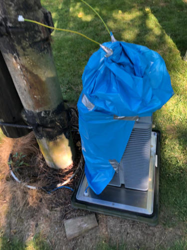
Below you see the out door placement of the unit with some enhancement for my antennas..
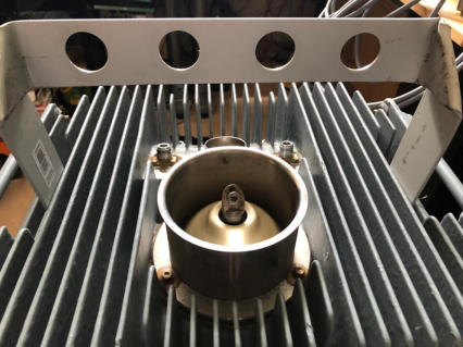
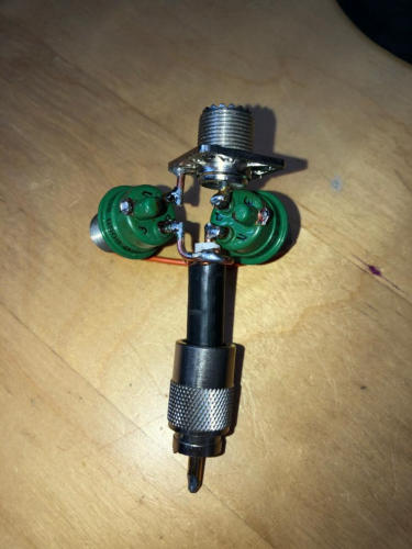
Enhancement for additonal external antenna connections
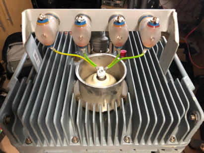
Build a holder for 4 additional vacuum relay to support my
already in use two Inv-L Antennas with 24m and 35m length.
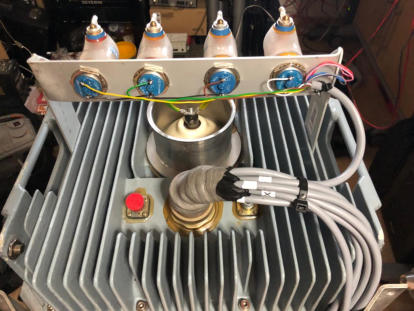
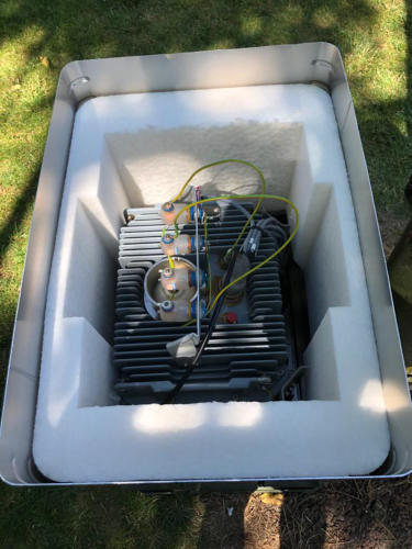
Lower left, AntennaTuner placed on base plate of additional
housing. Old ground lines from burried radial system, coax
cable to station and vertical 10m GP antenna feed through
from the buttom.
New RemoteControl unit mounted to FK310 unit.
First antenna tests and provisional protection for the night.
Final test of Remote AntennaTuner Unit / Final Matching
After final housing installation I had to re-tune my previous settings. Reason was
the vertical coax cable to the vertical GP antenna.
The feedline to the GP antenna build a ground wire to the vertical part of the
Inverted-L Antenna. Therefore I build an additional circuit to open both parts of
the coax cable to isolate the GP from the Inverted-L Antenna with good success
(checked by RF Current Meter, MFJ-854).
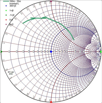
Below you see the impedance curve for my 35m Inv-L Antenna for the 160m band
measure with my microham SMORF vector signal meter. With this meter I can
configure to coax cable type and length and automatically the transformation
parameter will be calculated and displayed in the SMORF application.
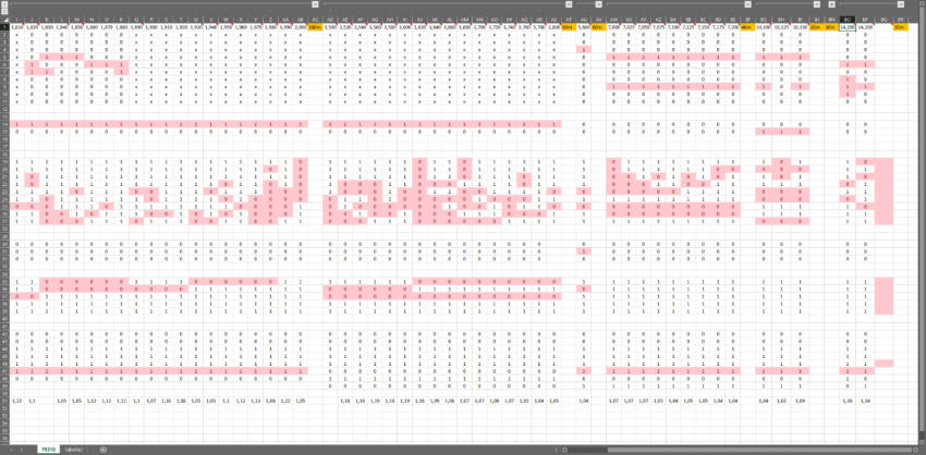
In an excel spreadsheet I collected all data to create the CAN message to Remote
AntennaControl unit..

New Housing tailor-made for its final use
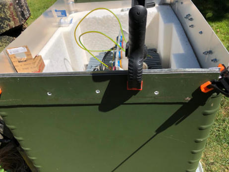
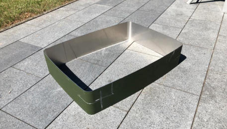
New housing had a total height of 140cm and was 20cm to high. With an electrical fox tail I cut out this extra length
(see lower right. This material was then used to build additional top cover guides.
On the lower left you see the top cover with two additional high voltage throughputs for the final antenna connection.
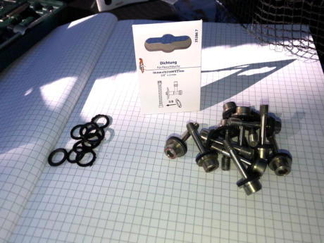
The old sealing rings was frayed and I renewed them to ensure tightness for the AntennaTuner.
After final housing installation I had to retune my previous settings. Reason was the vertical coax cable to the vertical GP antenna installed
on the top of the same wood mast for the Inverted-L Antennas.
The feedline to the GP antenna build a ground wire parallel to the vertical line / part of the Inverted-L Antenna. Therefore I build an
additional circuit to open both parts of the coax cable to isolate the GP from the Inverted-L Antenna with good success (checked by RF
Current Meter, MFJ-854).
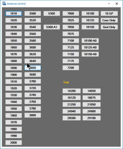
First application to send control messages (via CAN bus) to Remote AntennaControl
First software application executed on PC in the shack to perform
the remote control of the Remote AntennaControl manually by
pressing the dedicated button.
You see that I´m using different segments for each band.
Mainly due to the need of the narrow tuning bandwidth.
Only LC or CL high - / low pass tuning circuits used, without chance
to tune something…
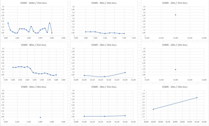
Below you see the results from first tuning session for all bands.
You see for all bands the VSWR setting below 1:1.3 => perfect match for operation.
DH1RK


Navigate
Navigate


- FK310 AntennaTuner
- Setup 2008
- Inverted L - Simulation
- Inverted L - Installation
- Inverted L - Matching
- SteppIR - Simulation / 20m band
- SteppIR - Simulation / 17m band
- SteppIR - Simulation / 15m band
- SteppIR - Simulation / 12m band
- SteppIR - Simulation / 10m band
- SteppIR - Simulation / 6m band
- SteppIR - Simulation Overview
- SteppIR - Installation
- HighBands -Yagis
- HighBands -Groundplanes
- Setup 2005