S-Match
S-MATCH© - A symmetrical and universal ATU
(PA0FRI's "S-MATCH ATU" published in RSGB's RadCom March 2003)
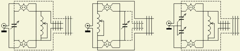
Variation of the design.
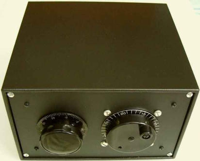
A model of the third variation…
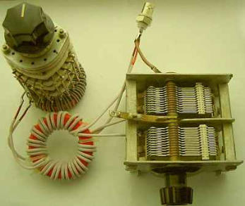
Home brewed with cleaned and painted components from the junk
box.
S-MATCH
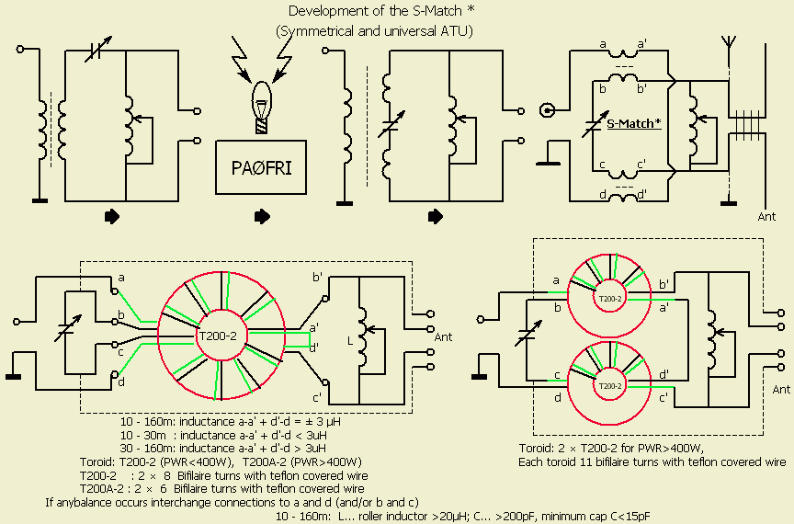
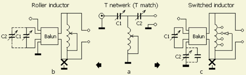
This symmetrical system, I call my design S-Match©, with one roller-inductor and one capacitor really works for balanced outputs. Input and
output circuits are isolated, so the system is also suited for single-wire antennas and coax feed antennas.
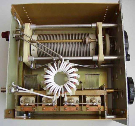
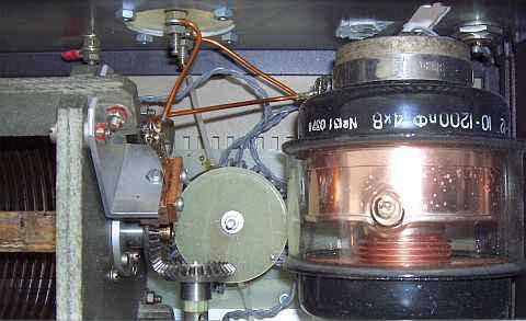
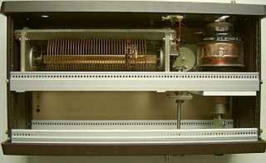
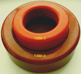
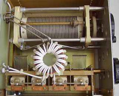
In my recent ATU the balun or transformer (T200A-2) is fixed (fig») with two PCB disks and
mounted between the 50 µH roller-inductor and the 12-1200 pF vacuum-cap.
CAPACITANCE
I can match my present antenna system even with 200 pF on all nine HF bands but my S-Match is built with a 1200 pF vacuum C. With that
capacitance I was able to match a friend's antenna on all HF bands. It was barely adequate to match another's friend's 160 m loop antenna.
So I fitted later on an extra-switched fixed 1200 pF in parallel into in my ATU in order to cope with any impedance.
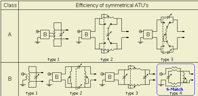
The efficiency is a little less than with a system using two capacitors and roller inductor or two roller inductors and one capacitor, but in
practice, the difference is minimal.
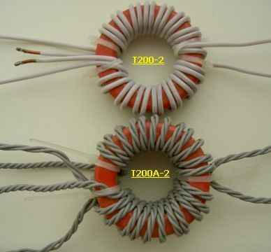
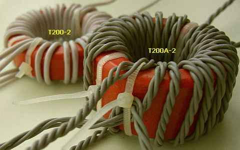
TRANSFORMER
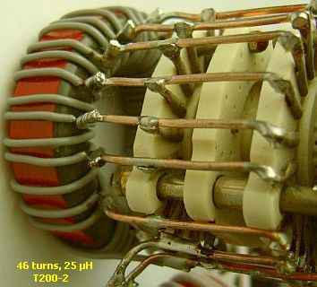
Transformers with Amidon toroids. The T200A-2 toroid is a nearly exact substitute for two T200-2 units sandwiched together.
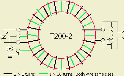
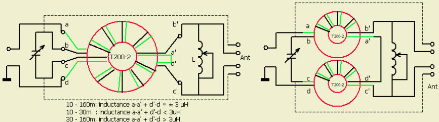
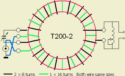
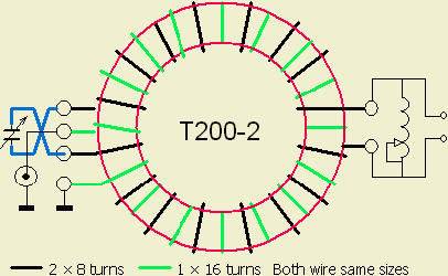
The inductance of the turns is a part of the resonant circuit with the roller-inductor and the capacitor. The rule-of-thumb for the windings is:
ATU for 10 – 160 m: ± 3 µH
ATU for 10 – 30 m: ≤ 3 µH
ATU for 30 – 160 m: ≥ 3 µH
The transformer or balun is part of the tuning system, most ferrite toroids are not suitable for high power but the indicated Amidon powder
iron core is. The windings should provide high-voltage insulation e.g. Teflon covered wire.
With some antenna systems a better efficiency can be obtained when the antenna is connected as shown by the dotted line.
IMBALANCE
If any imbalance occurs try the other connection or interchange the connections to the roller inductor.
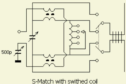
SWITCHED INDUCTOR
If a roller-coaster inductor is not available an extra capacitor in
series with the input will reduce the VSWR.
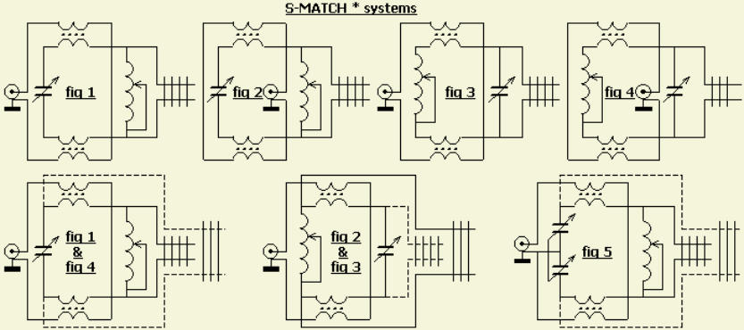
REPEATED TEST OF THE DESIGN
At present my favourite systems are fig 2 and fig 5.
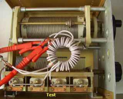
Recently the design was tested (fig») for efficiency and balance. It turns out that the balance of the four ATU's was almost identical. The best
balance was obtained with the schematic of figure 2 and figure 5
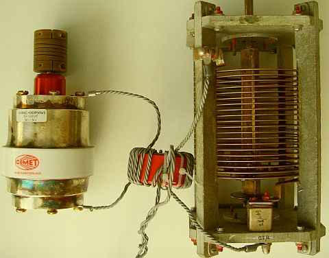
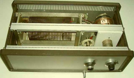
Test of the figure 5 design. The capacitor is suited for a
400W ATU but survives a test with 700 W on 80 and 160 m!
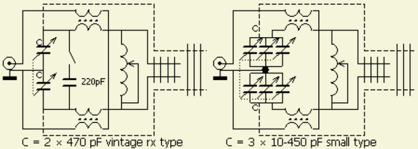
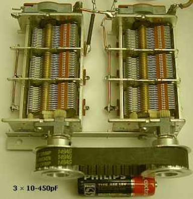
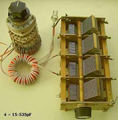
These small caps are suited for at least a 100 W ATU.
This simple ATU with capacitors from vintage receivers and a
T200-2 toroid switched inductance is suited for 400 W. All
pictures are just illustrative examples of this S-Match design.
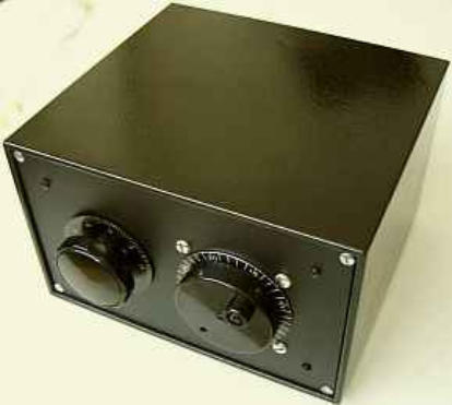
CONVERSION
A T-match unit can easily be converted to an S-match by removing the second capacitor or bypassing the first capacitor. The free hole in the
front panel of a converted commercial unit can be used for a switch for paralleling fixed capacitors to the tuning capacitor to provide
additional capacitance.
COMMENTARY
Since I published this design, may hams successfully copy this simple ATU.
One of the selected emails are presented here:
Ich habe wieder einmal etwas von deiner ufb homepage nachgebaut, eine S-Match ATU. Ich habe hier 3 verschiedenen ATU's und diese auch
alle 3 getestet.
1.
Drake MN2700 mit externem 1:4 Balun
2.
Parallelkreis Koppler ähnlich Johnson oder Annecke
3.
S-Match nach PA0FRI
Als Antenne verwende ich hier eine 2 × 20 m Dipol symmetrisch mit 240 Ohm Schlauchkabel (Antennenkabel für UHF-Fernsehantennen aus
den 70er Jahren) gespeist. Antenne hängt zwischen 15 m und 9 m über Grund.
Mit allen 3 Antennen erreiche ich von 160-10 m 1:1 SWR... die Ergebnisse vieler Tests sind folgende Reihenfolge:
1.
S-Match auf allen Bändern Nummer 1
2.
Parallkreis nach Annecke Nummer 2
3.
Drake Tuner Nummer 3
Du siehst dein S-Match ist der beste ATU, hinzu kommt noch die komfortable Bedienung. Ich habe den hier mit einer riesigen kommerziellen
Rollspule 14 µH und einem 20-200 pF Sendedrehko aufgebaut. Als Ringkern verwende ich im Moment noch 1 Amidon T200-2, werde den
aber gegen eine 2 Ringkernlösung mit 2 x T200-2 ersetzen, da der eine Kern bei 1 kW Output doch etwas warm wird.
Nun zu meinen Beobachtungen mit der S-Match. Bei 160 m benötige ich nur ca 7 µH der Rollspule und ca 400 pF für den Drehkondensator
(ich hatte eigentlich damit gerechnet dass die Rollspule zu wenig Induktivität auf 160 m hat). Bei den höheren Bändern wird das L natürlich
noch kleiner (auf 10 m habe ich noch 1 Windung der Rollspule). Trotz dieser sehr kleinen Werte ist die S-Match immer noch die beste auf
allen (!) KW-Bändern.
And:
Ich habe eben provisorisch Ihren S-Match mit alten Teilen aus der Bastelkiste auf Brett zusammengeloppt und getestet. Bauzeit: Gerademal
eine halbe Stunde (inklusive dem Wickeln der 2 Trafos (T184: 2 × 8 Windungen 1.5 Schaltdraht für 3µH).
Fazit: Alles problemlos!!!- Ich bin restlos begeistert und werde mir ein paar reguläre Geräte davon bauen.
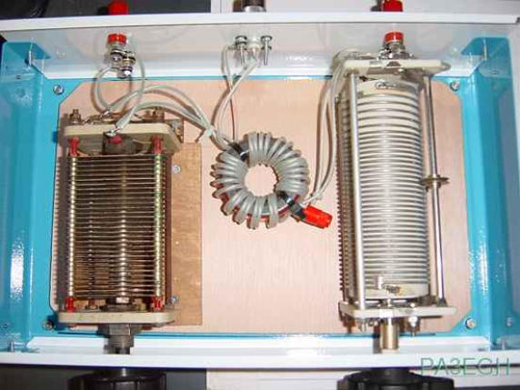
PA3EGH's S -Match
DH1RK


Navigate
Navigate


- FK310 AntennaTuner
- Setup 2008
- Inverted L - Simulation
- Inverted L - Installation
- Inverted L - Matching
- SteppIR - Simulation / 20m band
- SteppIR - Simulation / 17m band
- SteppIR - Simulation / 15m band
- SteppIR - Simulation / 12m band
- SteppIR - Simulation / 10m band
- SteppIR - Simulation / 6m band
- SteppIR - Simulation Overview
- SteppIR - Installation
- HighBands -Yagis
- HighBands -Groundplanes
- Setup 2005